2019 Seismic Design Competition
This blog is about the engineering behind a winning third place structure at the 2019 Seismic Design Competition in Vancouver, BC Canada.
Keywords: Topology Optimization, ETABS, REVIT, Presentation, Teamwork
1. Competition Problem Statement
The participating team is tasked with the design and construction of a structure made from Balsa Wood. The structure is then evaluated by the following criteria: (1) Annual Revenue based total floor area, (2) Annual Building Cost based on weight and adhering to structural requirements, and (3) Annual Seismic Cost based on the structure’s seismic performance and displacement prediction. The structure will be tested on a shaking board imitating an earthquake event and the ground motion details are given for the design. There are 2 ground motions representing a medium and heavy earthquake. Dead loads in form of steel rods and bolts are added to further test the structure. For more details on the rule of the competition, the readers can download this document.
The competition is held in Vancouver, British Columbia and includes a lot of excellent univeristies around the world (i.e., Stanford, Cornell, UC Berekely, etc..) and our team at the University of Memphis ranked third in the competition. For the full video of the events and our structure’s performance (starts at 35:34) on the earthquake, please follow this link: https://fb.watch/adztRYe8lL/
2. Structural Engineering
Seismic Load Mechanism: Due to the acceleration of the ground relative to the structure itself, we can earthquake forces is a ficticious force acting horizontally on any object with significant mass. This force is very similar in direction and behavior to wind forces. Therefore, the building behaves much like a cantilever beam where the maximum moment is occuring at the bottom of the building.
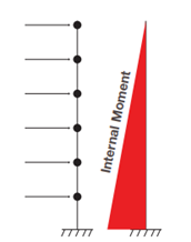
Figure 1. Illustration of Seismic Load
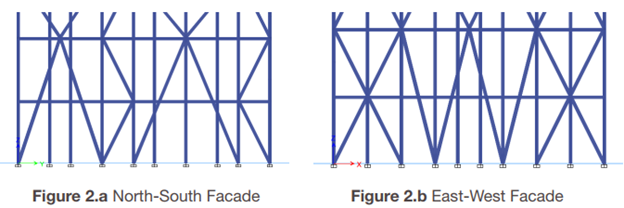
Figure 2. Lobby Bracing
Horizontal In-plan Bracing due to Structural Irregularity: The building maximum footprint as defined in the rule has a t-shape and thus, it introduces structural irregularity into the analysis. The center of diaphargm does not lie in the middle of the floor plan. Therefore, the earthquake will have an effect on the floor in the same way that a torsional force is applied on a T-beam. Therefore, we add diagonal bracing to the floor since the beams alone are not enough to withstand this force.
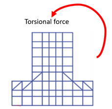
Figure 3. Torsional Force
Structural Bracing Topology Optimization: The term topology optimizationis a process of finding a better topology in increasing structural strength against a specific type of load (i.e., earthquake) with less material. The traditional bracing for lateral load is an X-frame. However, we use a different type of bracing namely super bracing. The analysis shows that it has twice the strength-to-weight ratio compared to X-bracing. The rationale of super bracing is to distribute less load to the outer columns since it is the member with the lowest Euler critical buckling load due to its longer length.
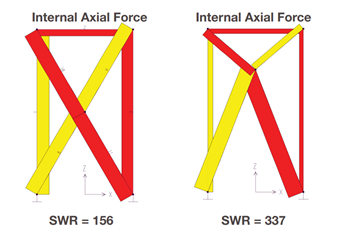
Figure 4. Topology Optimization with X-bracing (left) and Super Bracing (right)
Structural Analysis The building is first modeled in Revit Structure. Revit allows a 3D model of the structure and from which, several technical drawing plans are exported for the real construction. The architecture rendering is based on this 3D model too. In terms of structural analysis, the author used ETABS with the technique of Response spectra analysis. The results gathered are (1) would the structure survive the earthquake? (2) Rooftop displacement prediction, and (3) Structural members’ internal force. As expected, we see a lot of internal forces on the beams of the floor plan due to torsional and axial forces on the columns at the lower stories and lobby.
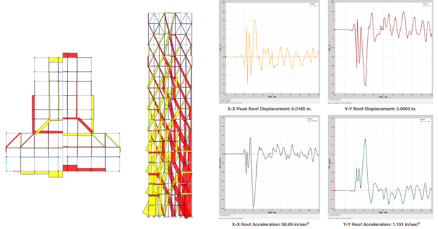
Figure 5. Result from ETAB Analysis
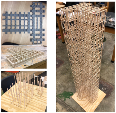
Figure 6. Construction of the Building
Author's Contribution in this project
The author is the main person that works on the structural design of this structure. This includes research on seismic load mechanism, reinforced lobby structural, horizontal inplan bracing, and topology optimization. The author also carries out the modeling in Revit and analyzing in ETABS. The poster and presentation are designed and presented by the authors. However, the construction of the structure relies on the other team members.
Additional Resources
Link to Poster Link to Presentation Photos from the competition